


31
2024
-
10
Technology frontier: molded optical glass lens
概述: For optical engineers and lens designers, chalcogenide compounds (ChG) are rapidly becoming the infrared material of choice. Chalcogenide is an amorphous glass that is easier to use than traditional infrared crystalline materials. There are many different chemical composition options for chalcogenide compounds, but BD6, which is composed of arsenic and selenium (As40Se60), is the best choice in terms of cost and ease of manufacture.
Technology frontier: molded optical glass lens
For optical engineers and lens designers, chalcogenide compounds (ChG) are rapidly becoming the infrared material of choice. Chalcogenide is an amorphous glass that is easier to use than traditional infrared crystalline materials. There are many different chemical composition options for chalcogenide compounds, but BD6, which is composed of arsenic and selenium (As40Se60), is the best choice in terms of cost and ease of manufacture.
Compared with other infrared materials, BD6 has many advantages, including high refractive index, low cost (partly due to the absence of germanium components), light weight, non-thermal properties, high transmittance, and flexible manufacturability. BD6 has a refractive index of 2.75-2.85 across the infrared spectrum, making it a very suitable material for optical components. With a density of 4.63g/cm3 and light weight (compared to other infrared materials), BD6 is ideal for weight-sensitive applications such as aerospace.
BD6 costs less than most other durable infrared materials. BD6 has a low thermo-optic coefficient (dn/dt) of 30 × 10-6, which helps designers achieve better non-thermal performance. The transmission of uncoated BD6 glass in the whole infrared spectrum is higher than 60%. ISPOptics company provides high-efficiency broadband anti-reflection (HEAR) film for BD6, with an average transmittance of more than 95% in the long-wave infrared (LWIR:8 ~ 12μm) band.
infrared optical material
Designers can use a variety of infrared (IR) optical materials. When designing an infrared optical element, a number of factors related to the optical material used must be considered. These factors include refractive properties, optical transmission, non-thermal properties, hardness/durability, environmental sensitivity, weight/density, manufacturing technology, and cost. Some of these factors are interrelated. For example, for some materials, their optical transmittance is high at room temperature, but decreases at higher temperatures. Considering all these factors, when designing infrared optical components, material selection needs to be carefully considered.
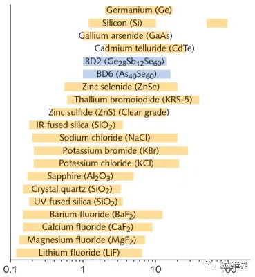
Many materials suitable for infrared optical components, including chalcogenide glass, semiconductors, water-soluble crystals, etc.; chalcogenide glass is shown in blue.
Before the popularity of chalcogenide compounds, semiconductor materials have been the traditional main infrared materials. For example, germanium has historically been the most popular infrared material, it has several advantages, including the highest refractive index of all infrared materials (~ 4), it is easy to process with diamond, it naturally blocks ultraviolet, visible, and near infrared light (up to ~ 2 μm), and it also has high transmittance in the MWIR and LWIR bands. However, germanium does have its drawbacks, including high material cost, high thermo-optic coefficient (resulting in poor thermal insulation properties), and very high density and high weight. Ge in particular is prone to thermal runaway, so the material becomes completely opaque at higher temperatures. Other semiconductor materials do not have trade-offs like germanium. For example, Si has a very low density, making it more suitable for weight-sensitive applications. However, Si absorbs heavily in the 8-12 μm range and is therefore not suitable for use at these longer wavelengths.
Zinc compounds provide many benefits for infrared applications. For example, zinc selenide provides high transmittance in the infrared spectrum (below 16 μm), high refractive index, strong thermal shock resistance, and ease of diamond processing. The thermal shock resistance of this material makes it ideal for high power laser applications. Zinc sulfide is another zinc compound used as an infrared material, providing high transmittance to 12 μm in the infrared band, low absorption, and can be processed using diamond. Furthermore, although both ZnSe and ZnS are transmissive to visible light, they are not moldable and are even more expensive than Ge.
Zinc selenide is a commonly used infrared optical material with a large spectral transmission range, but it is expensive and non-moldable.
For very cost-sensitive infrared optical applications, water-soluble crystals may be a good choice. They are among the cheapest optical materials with high transmittance deep into the infrared and visible light. Of course, water-soluble crystals also have deficiencies. They are highly hygroscopic materials, so for most applications a moisture barrier membrane layer is required. In addition, many water-soluble crystals are soft and brittle, which means they cannot be machined using diamond. The main application of water soluble crystals of this type of infrared materials is the window in the gas/liquid sample cell of the spectrometer. In addition, potassium chloride (KCl) is used to make the protective window of a carbon dioxide (CO2) laser because KCl has a low refractive index and a high damage threshold at 10.6 μm.
For infrared applications where high luminous flux is a priority, CaF2 has its advantages. The transmittance of uncoated CaF2 is higher than 90% to 7 μm, and it is highly transmissive in the near infrared and MWIR bands. Thus, this means that manufacturing is generally simplified when such materials are used, since an AR film layer is generally not required. Although CaF2 is a brittle material, it can be machined with diamond. Unfortunately, CaF2 is also quite hygroscopic, which also affects its use. Like CaF2, the transmittance of uncoated barium fluoride (BaF2) is higher than 90%, but the transmission wavelength is farther than CaF2, reaching 9.5 μm. Also, like CaF2, BaF2 can be machined with diamond. But BaF2 is very susceptible to thermal shock and is more expensive than CaF2. Fluoride materials are not moldable.
More Materials for Infrared Optics
For example, anhydrous (also referred to as IR grade) fused silica is an amorphous glass material with good transmission in the near infrared (to 3.5 μm) and good non-thermalization properties. However, because this material is very hard, it cannot be processed with diamond. This makes it more difficult and expensive to manufacture aspheric optical elements using fused silica.
Sapphire is a harder material (second only to diamond in terms of hardness) and cannot be machined with diamond. However, it is very durable, and it can withstand extremely harsh environments with a melting point of more than 2000°C. Sapphire also has an uncoated transmittance of up to 5.5 μm. Due to the low dn/dT, sapphire is well suited for non-thermal applications.
Chalcogenide glass belongs to non-oxide glass, which is an amorphous glass material formed by the combination of chalcogen elements and other metals or non-metals. Compared with germanium single crystal, chalcogenide glass contains less precious metals and has lower relative cost. At the same time, chalcogenide glass has good transmittance, very low refractive index temperature coefficient and dispersion performance, its refractive index can be adjusted by the basic formula of the glass, can be used in conjunction with other infrared materials, applied to virtual color correction, no thermal defocus infrared optical system, become an ideal material for optical designers to design no chromatic aberration, no thermal defocus optical system. In addition, compared to infrared crystal materials can only use single-point diamond turning processing aspheric status quo, chalcogenide glass crystal materials do not have the advantages of precision molding molding, mass molding production can greatly reduce processing costs.
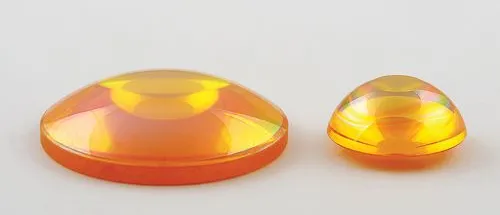
Chalcogenide glass color dark, the naked eye can not see any glass should be transparent, if not specifically pointed out, few people think it is a kind of glass, more may think it is graphite or a black metal material. Ryukyu glass can transmit infrared rays and is a "transparent" material that is extremely sensitive to temperature. The reason why chalcogenide infrared glass has this special function is that it is an amorphous material formed by the combination of chalcogen elements (sulfur, selenium, tellurium) and other metal elements (gallium, germanium, etc.). It has excellent mid-and far-infrared transmission performance and is widely used in infrared night vision, infrared temperature measurement, infrared thermal imaging and other fields.
Characteristics of chalcogenide glass
1. Optical performance parameters
Infrared transmittance: far infrared transmittance is greater than 64% (wavelength 8μm ~ 12μm), and the transmittance can reach more than 95% after coating.
Refractive index (nλ): The refractive index of chalcogenide glass is as high as 1.7-2.4, which makes it widely used in the field of optical communication and optical sensing. The refractive index temperature coefficient is small, for example, the refractive index temperature coefficient of Gasir-1 is only 49.7 × 10 − 6/℃, so it plays an important role in the thermal defocus adjustment and chromatic aberration correction of infrared thermal imaging system.
Dispersion coefficient: The dispersion coefficient of chalcogenide glass is low, which makes the use of chalcogenide glass in achromatic and non thermal optical design.
Density (ρ,g/cm³): The density of chalcogenide glass varies depending on the composition and preparation process. For example, the density of IRG101 is 3.20g/cm³, and the density of IRG102 is 3.10g/cm³.
2. Physical property parameters
Thermal stability: Chalcogenide glass has a soft structure, low softening temperature, low hardness, low Tg and Ts temperature, and is suitable for precision molding of aspheric lenses, which is beneficial to reduce the production cost of mass lenses. Therefore, chalcogenide glasses can provide low-cost IR optical elements for the rapidly developing infrared technology field.
Chemical stability: the chemical stability of chalcogenide glass mainly refers to the glass in alkali, acetone, alcohol and other organic substances contact, the glass internal elements and do not occur chemical reaction.
Temperature adaptability: Chalcogenide glass can face a temperature difference of 110 degrees from -40 ℃ to 70 ℃ without pressure, and still keep the image stable.
Molded Ryukyu Glass
The manufacturing process of chalcogenide glass is also very different from traditional glass melting. It uses vacuum melting technology, the purity of 99.9999 raw materials in a vacuum environment after high temperature precision dissolution, and quickly complete the glass forming. From the melting of chalcogenide glass materials, to the precision molding of spherical and aspheric lenses, to the coating assembly of finished lenses.
The molding process realizes the pressing molding of aspheric precision optical elements, which not only creates an era in which optical instruments can use aspheric glass optical elements, but also brings new changes and developments to the optical system design of optoelectronic instruments. Molded lens technology not only saves the cost of raw materials, but also improves the performance of optical instruments and improves the quality of optical imaging.
forming method
In a non-oxidizing environment, the glass and the mold are heated together to a temperature in the vicinity of the softening point of the glass, and the glass is pressed by the mold under the condition that the glass and the mold are at substantially the same temperature. Next, the mold is cooled under the condition of maintaining the applied pressure to reduce its temperature to below the transformation point of the glass. This method is called isothermal pressurization method. In order to prevent the glass after heating and softening from adhering to the mold, the selection of the material for manufacturing the mold is also very critical, so that it is easier to obtain the ideal shape and surface accuracy and is not easy to produce bubbles and cold mold traces, precisely copy the lens from the mold shape surface. However, it takes a long time to heat up and cool down, so the production speed is very slow. The method is then optimized by using several moulds in one moulding device in order to increase the production efficiency.
Types and blanks of glass
The quality of the glass blank is directly related to the quality of the molded product. According to the truth, most of the optical glass can be used to mold into molded products. However, the glass with high softening point, due to the high forming temperature, has a slight reaction with the mold, resulting in a short service life of the mold. Therefore, from the viewpoint that the selection of the mold material is easy and the service life of the mold can be extended, it is necessary to develop a glass suitable for press molding at a low temperature (about 600 ° C.). However, the development of glass suitable for low-temperature press molding must meet the requirements of being able to manufacture blanks inexpensively and not containing environmentally polluting substances (such as PbO, As2O3). There are requirements for the use of glass blanks for molding:
The surface of the blank before the pressure must be kept very smooth and clean;
② Proper geometric shape;
The required capacity. Blanks are generally selected spherical, round cake or spherical shape, using cold grinding molding or hot pressing molding.
Mold Materials and Mold Processing
The mold material needs to have the following characteristics:
① The surface is free of defects and can be ground into a smooth optical mirror without pores;
It has high oxidation resistance under high temperature conditions, and the structure does not change, the surface quality is stable, and the surface accuracy and smoothness remain unchanged;
No reaction with the glass, adhesion phenomenon, good demoulding performance;
It has high hardness and strength under high temperature conditions.
At present, there are many patents related to the development of mold materials. The most representative mold materials are: cemented carbide as the substrate, with precious metal alloy and titanium nitride and other thin films on the surface; Silicon carbide and superhard alloy as the substrate, with hard carbon, diamond-like carbon and other carbon films on the surface; and Cr2O-ZrO2-TiO2 new ceramics.
Mold materials are generally hard and brittle materials. In order to precisely process these mold materials into molds, high-rigidity ultra-precision computer digital control machine tools with high resolution and resolution below 0.01μm must be used to grind diamond grinding wheels. The grinding process can obtain the desired shape accuracy, but then it needs to be slightly polished and finished into an optical mirror. In the process of high-precision aspheric machining, aspheric surface testing and evaluation technology is very important. For the processing of the micro lens molding die, the requirements are more stringent, and it is necessary to further improve the accuracy and reduce the grinding marks.
Mold processing
The glass process of molding directly inside the metal insert is similar to the embedded plastic injection molding process, but there are significant differences in nature due to the differences in processing temperature, material characteristics and manufacturing requirements. Despite certain limitations, embedded glass precision press molding (IPGM) technology offers numerous advantages to product designers.
The IPGM process is carried out above the transition temperature of the glass, which requires that the thermal properties of the metal insert material must be compatible with the glass in order to avoid excessive stress on the glass during the forming process or residual large stresses in the glass article after forming, both of which can lead to glass cracking, birefringence or failure due to thermal cycling. This article will explore the technology and specific design elements that must be considered when designing IPGM products.
Glass precision press molding
Glass Precision Press Molding (PGM) technology is an advanced manufacturing process for the production of high quality aspheric optical lenses. The technique involves shaping a glass preform by high temperature press molding in a tightly controlled environment. Schaub et al. have elaborated on the PGM process, and the following is a brief review of the PGM process. A flow chart of the process is shown in Figure 1, while the temperature, pressure and time records are shown in Figure 2. Figure 1 shows a simplified process for single-cavity glass molding, which may vary in practice.
The PGM process flow begins with the fabrication of a lens mold. The mold generally consists of an upper mold, a lower mold, and a number of auxiliary molds to form the shape, diameter or other characteristics of the lens. Additional mold sets may also be required to ensure alignment between the mold halves. After the customized mold is completed, install it into the glass molding machine, as shown in Figure 1-(1). Next, the glass preform is placed in the mold stack, as shown in FIG. 1-(2). Then the top mold is reinstalled and the air is removed, as shown in Figure 1-(3). Thereafter, the mold stack and glass preform are heated at a controlled rate, as shown in FIG. 1-(4). The final processing temperature will depend on the type of glass used. When the appropriate temperature is reached, pressure is applied to the preform to start the lens forming process, as shown in FIG. 1-(5). The pressure applied to the glass is controlled throughout the forming cycle; after forming is complete, the pressure is removed. The die set is typically cooled by an inert gas purge system. In order to produce lenses in a cost-effective manner, the cooling step is designed to shorten the cycle time as much as possible, as shown in Figure 1-(6). After the final product has cooled to a processable state, the components are removed, as shown in Figure 1-(7), and then the next production cycle is started, as shown in Figure 1-(8).

Figure 1-Glass Precision Press Molding Process Flow

Figure 2-Typical Glass Precision Molding Process
Embedded glass precision press molding
Embedded glass precision press molding (IPGM) occurs during the introduction of metal inserts into the lens molding process, with the purpose of manufacturing a finished product composed of two separate parts in a single process. This additional component is typically a machined metal component that serves as a mounting means for the molded glass lens.
Metal inserts must maintain their physical properties unchanged during PGM operation, thus requiring them to have a melting point above the glass transition temperature. When selecting a metal insert material, special consideration is given to its coefficient of thermal expansion (CTE), which is an important indicator for ensuring thermal compatibility between materials. The insertion of metal inserts is performed before the initial heating stage, which requires that the mold design must be adjusted accordingly to accommodate the inserts, so a customized mold is required. The entire embedding process follows the operational steps consistent with the flow documented in FIGS. 1 and 2.
Table 1-Coefficient of thermal expansion of moldable glass
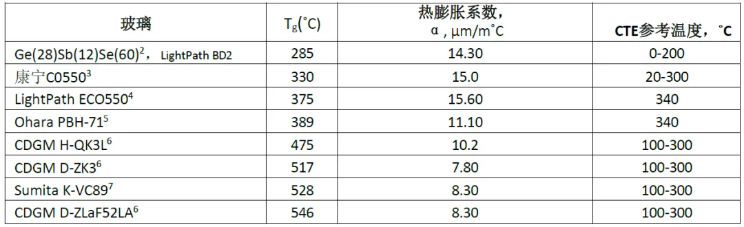
Embedded glass precision press molding (IPGM) technology has made great progress since it was patented in 1993. Initially, this technology was mainly used to produce small optical components used in the telecommunications industry. In the early days, lens products mostly used lead-based glass, which has a lower glass transition temperature and a higher coefficient of thermal expansion, such as Ohara's PBH71 or Corning's C0550, which is shown in detail in Table 1. However, due to environmental protection regulations, these lead-based glass materials and many other lead-containing glass materials are gradually eliminated from the market. At present, the market is more inclined to use environmentally friendly glass materials, these materials not only have a higher glass transition temperature, but also a lower thermal expansion coefficient, such as CDGM D-ZK3, D-ZLaF52LA, and Sumita K-VC89.
With the increasing demand for larger diameters, more shape variations, and a variety of insert materials, an in-depth understanding of the IPGM process becomes particularly critical. This demand urges us not only to be satisfied with the traditional understanding of small diameter, single or a few glass materials and single metal inserts, but also to take a more comprehensive and detailed perspective to examine the IPGM process. Therefore, the purpose of this paper is to provide a more detailed and in-depth analysis of the IPGM process, aiming to go beyond the previous literature on the discussion of the process, to provide a richer content and more detailed analysis.
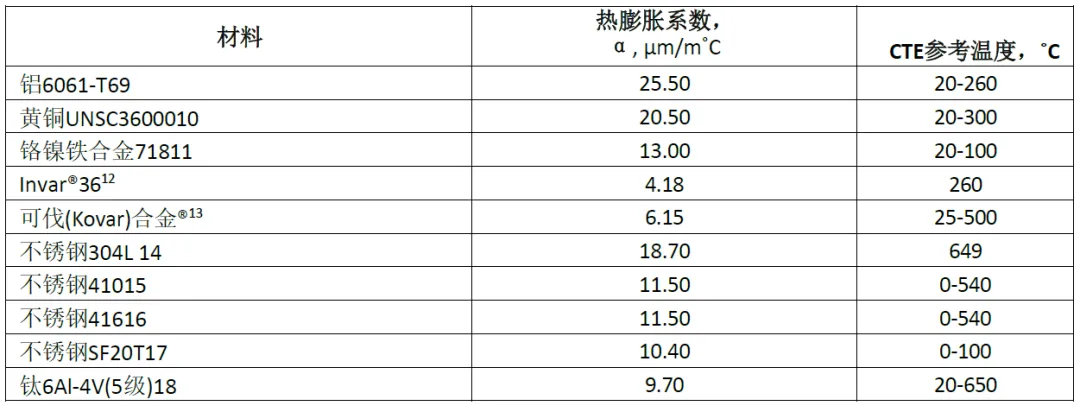
Figure 4-Insert Molding IPGM Process Steps
Molding process design
Material selection
When designing embedded glass precision press molding (IPGM) products, the first step is to carefully select suitable optical glass and metal insert materials. Usually, optical glass is selected before metal inserts because the product needs to meet specific optical performance requirements. After determining the glass type and completing the optical design, you need to match the selected glass with the appropriate metal insert material. The selection of metal inserts requires a combination of factors to ensure that all final assembly characteristics meet the common criteria of the IPGM process, particularly differences in coefficient of thermal expansion (CTE), which will be discussed in more detail later. Table 2 shows some possible insert material options.
Key assembly characteristics that affect insert material selection include cost, weight, material availability, magnetic properties, weldability, and low outgassing of the material for high vacuum applications. After considering all the above factors, the CTE of the selected material must fall within the acceptable CTE range of the glass used. In practical applications, there are mainly two situations: the first is that the CTE of the glass is higher than that of the insert material; the second is that the CTE of the insert material exceeds that of the glass. In theory, there is also a third possibility that the CTE of the glass and the insert material are exactly equal, which means that the expansion and contraction rates of the two materials are the same, resulting in a net zero stress inside the component. However, such cases are extremely rare in reality.
Case 1: Glass CTE> Metal Insert CTE-Tensile
Case 2: Glass CTE
In case 1, the glass shrinks faster than the scaffold material after the lens is formed in step 5 in FIG. 2. The glass will try to pull away from the bracket. If there is a material interaction between the glass and the bracket, tensile stress will be generated in the glass, or the glass and the insert will not become a single element. In Case 2, after formation, the scaffold shrinks faster than the glass, placing a compressive stress on the glass and forming a single element, or if the CTE mismatch is too large, the stress from the insert may cause the lens to crack. This CTE range varies slightly depending on the mechanical design of the insert, which will be discussed later. At this point, the range of embedding materials can be narrowed down and the final selection can be made. In general, the ratio of the insert inner diameter (which is the same as the lens outer diameter in the case of IPGM) to the insert outer diameter affects the feasibility of certain materials and their respective CTE values. Lowering this ratio can help lower the stress value, allowing combinations that are not normally considered.
Table 2-Thermal expansion coefficient of selected metal insert materials


Figure 5-Variation of thermal expansion coefficient of metal insert material with temperature
Once the materials are selected for the final assembled product, calculations can be used to estimate the pressure on the lens created by the thermal contraction of the insert to determine the feasibility of the design. The interface pressure generated between the outer diameter of the glass and the inner diameter of the insert may have an impact on the manufacturing component. If the pressure is too high, the assembly has a tendency to crush the glass and break it as it cools. On the other hand, if the interface pressure is too low, the lens may fall out of the final assembly or fail to meet the push-out test criteria.
The insert molded lens is similar to the classic case of press-fitting two cylinders, so the calculation of the interface pressure between the glass lens and the metal holder can be done using the same equation, but with minor modifications. In the case of press-fitting two cylinders together, the interface pressure is formed due to the interference fit and the shrinking material: Equation (2.1) is shown below 19. The interface pressure p is related to the total material interference δint and can be solved by the following equation 2.3. R is the transition radius, Ei is the modulus of elasticity, and vi is the Poisson's ratio of the material.

(2.1)
Equation 2.1 applies to similar materials. In the case of IPGM, the interference is caused by the different thermal expansion of the different materials, in particular the contraction or expansion of the metal insert around the glass lens. When the molding operation is performed and the assembly is heated, the insert expands radially according to equation 2.2, where ΔD is the change in diameter of the insert, D0 is the initial diameter of the insert, α is the CTE of the insert material, and ΔT is the temperature difference between room temperature and the maximum temperature.

(2.2)
The coefficient of thermal expansion determines how the diameter of the insert changes with temperature. In this approximate case, it is assumed that the thermal expansion coefficient of the embedded material is linear in the temperature range determined by the highest processing temperature in Figure 2-(5). The highest processing temperature is used because the CTE of most materials varies with temperature.
This equation is solved for the maximum nominal diameter of the insert at the glass annealing temperature, and the viscosity of the glass preform is at a value that allows it to form the shape of the insert. After the molding process is complete and the assembly begins to cool, the insert contracts radially around the lens, creating an interference pressure. This pressure is estimated by first solving for the interference between the glass and the insert. This can be solved by the following equation 2.3, where δint is the total interference between the glass and the insert, αi is the CTE of the inner glass material, αo is the CTE of the outer metal insert material, and ΔT is the temperature difference between room temperature and the highest process temperature. Finally, R is the transition radius, or the radius to solve for the interface pressure.
(2.3)
Equation 2.4 is simplified by setting the inner radius to zero, thereby eliminating the inner radius or ri term in the right half. The equation for the interface pressure p is then solved algebraically. The solution is shown in Equation 2.5. Once the total mechanical disturbance Δr,v and the elastic modulus E of the insert and glass material are known from equation 2.4 (Poisson's ratio), they are then input into equation 2.5 to estimate the interface pressure generated by the shrinkage of the insert around the glass.

(2.4)

(2.5)
Once this interface pressure value is known, it can be used to determine the manufacturing feasibility of the design, and if necessary, the mechanical insert design can be optimized to increase manufacturability. After solving the interface pressure value, a finite element analysis model can be created in the CAD software program to evaluate the stress in the design. This is particularly useful for insert designs with complex features or when precise optical quality must be maintained. Effectively designing an IPGM lens does not require stress calculations, but rather uses the interface pressure calculations described above as an empirical design mold to determine where a particular design is located within the range of manufacturability.
Mold mechanical design
Industry-recognized good machining practices should be followed in the design of machinery, particularly in the design of inserts. The following different types of insert design features:
Type I insert: This design is the most basic form, usually presented as a simple ring structure. It has the advantage of low cost, minimal or no need for customization of the mold, and its stress distribution is simple and predictable. This design is favored for its economy and ease of manufacture.
Type II Insert: Compared with Type I, Type II design has some extension on the bracket so that it extends beyond the edge of the lens. This extension requires additional considerations in the mold design and therefore increases the cost of the mold. During the manufacturing process, the unsupported region of the holder (I. e., the glass portion outside the lens) may shrink faster than the supported region due to a drop in temperature, which may result in a stress differential or stress concentration at the interface of the lens and the extension holder. Such stress concentrations may adversely affect the performance of the product or the feasibility of manufacture.
Type III Insert: The Type III design is similar to Type II in many respects, but the difference is that the holder extends on both sides of the lens, which undoubtedly increases the complexity of the design and leads to a further increase in cost.
When designing an insert, cost, manufacturing complexity, and potential performance impact need to be weighed. Type I designs are often preferred for their simplicity and cost-effectiveness, but if the design requires the bracket to provide additional support or functionality, a Type II or Type III design may need to be considered, although this will bring higher costs and manufacturing challenges.
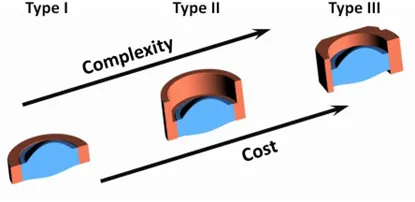
Figure 6-Types of IPGM Lenses
It should be noted that one of the most expensive components of PGM and IPGM process manufacturing is mold cost 1. The reduction in die life directly leads to an increase in component cost. Therefore, it is important to evaluate the impact of the design on the mold used to manufacture the product. IPGM's Type II and Type III inserts increase the processing steps and manufacturing cycle of carbide or ceramic tools, thereby increasing tool costs. Designs in which the lens is deeply recessed in the holder may shorten the life of the mold.
Figure 7 shows two concepts of the same design, and the design on the left looks simple and clear. However, this design creates sharp edge conditions in the mold. The sharp edge condition limits the useful life of the mold and can be difficult to manufacture. The design on the right is much stronger. By simply creating an extended relief, the mold geometry becomes easier to manufacture and more durable.
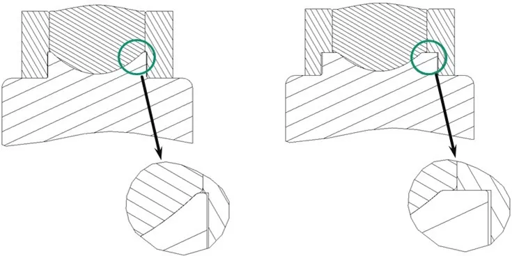
Figure 7-Impact of design on tooling: sharp edge conditions (left) and robust tooling design (right)
The IPGM process is a volumetric molding process. The volumetric molding process requires the volume of the preform to match the volume of the finished product. A spherical or spherical preform is the most common preform geometry used in PGM and is used as an example in FIG. 8 to show the proper volumetric fit of the preform within the insert. As shown on the left side of Figure 8, the ball preform must not only match the volume of the finished lens, but also must be able to introduce inserts during the manufacturing process in Figure 4-(2). This is clearly not the case on the right side of FIG. 8, the preform may be a volume fit, but the operator cannot place the preform into the insert. While this may seem like an obvious problem, it can easily be overlooked if you are not familiar with the volumetric nature of IPGM. Other preform shapes can be used to accommodate special designs, but these shapes are often associated with increased cost or loss of precision.
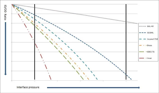
Figure 8-Fit of preform and insert: Pass (left) and not pass (right)
The mechanical properties of metal inserts in the IPGM design, in particular the wall thickness, are limited. These limits are mainly affected by standard machining tolerances, but in some cases, the precision molding process of metal inserts may also have a certain impact on the geometry of the insert. For any free standing wall feature (I. e., not in contact with an optical element), the typical minimum thickness is 0.250mm, and the height of a wall of this thickness typically does not exceed 1mm. Nevertheless, there are exceptions, and these need to be assessed on a case-by-case basis.
The thickness of the wall in contact with the optical element is limited by the calculation of the interface pressure. Keeping the optical design and the inner diameter of the insert constant, the ratio of the outer diameter of the lens to the outer diameter of the insert can be directly related to the interface pressure by equation 2.5. In the IPGM process, when the ratio of the inner diameter to the outer diameter of the insert is kept constant, the interface pressure will decrease as the ratio of the inner diameter to the outer diameter of the insert increases. The wall thickness of the insert must be sufficiently thick to produce an interface pressure value within a known success range. If the outer diameter of the insert is too large, causing the ratio to decrease, the interface pressure will increase, which may cause the lens to crack.
Figure 9 shows a typical relationship between the ratio of the inner diameter to the outer diameter of the insert and the interface pressure. Different combinations of glass materials, forming temperatures, and embedding materials will cause slight changes in the slope of the line. It is important to ensure that the interface pressure remains within an acceptable range and that the mechanical integrity of the final assembly is maintained. The acceptable range of interface pressure is based on experiment and experience. As the research progresses and data points increase, this range will become more precise.
Another unknown factor in insert molding is the influence of chemical interactions between the glass and different metals during processing. In some cases, it has been seen that the lens is actually in tension rather than compression, which is the case 1 above with regard to the thermal expansion part. This means that the lens will be released from the insert after molding. In some cases, however, the opposite is true 8. This article mainly discusses the compression case or case 2 from the thermal expansion part. Further research is needed to predict by design that the lens is in tension.

Figure 9-Inner Diameter to Outer Diameter Ratio vs. Interface Pressure
Complex finite element analysis can be done with CAD molds, however, for IPGM design, interface pressure values are used to create empirically designed molds. Stress calculations will take the design one step further. Stress in glass is a difficult parameter to predict, and even the latest CAD programs are difficult to calculate. Studies have been conducted to estimate how molding-induced residual stresses affect glass lenses. Tiny voids and scratches on the surface of the optical device will easily propagate with the introduction of stress. The surface quality of glass lenses has always been an issue in glass molding, and IPGM is treated no differently.
Advantages of molding mold insert molding
Insert molding offers many advantages to the designer. An optical lens molded in another component is easier to handle than a bare lens. The lens surface may be protected by an insert, as shown by the Type II and Type III brackets in FIG. 6. Mechanical features can be designed into the insert to facilitate the next level of assembly. Direct molding into the metal bracket also significantly improves the alignment of the lens optical axis with the mounting component as compared to similar adhesive assemblies. The bonding assembly will take into account three tolerances-the gap of the manufacturing assembly, the tolerance of the outer diameter of the lens and the tolerance of the inner diameter of the holder. Alternatively, using IPGM, the glass is molded directly into the bracket, essentially eliminating all three tolerance stacks. When the processed insert is placed into the molding machine, it is usually aligned on the precision mold, as shown in Figure 4-(1a). The mold is precision diamond ground, and the mounting features can even be constructed during the molding process that creates the optical surface. A properly designed IPGM assembly will also minimize wedges between the optical lens and the insert, which is sometimes difficult to minimize in a bonded assembly. By using precision diamond-ground mold surfaces to align the inserts, wedges can be greatly reduced. The only contribution is to maintain the tolerance of the support itself and the alignment of the mold and the insert.
Molded IPGM Manufacturing
Plug-in precision-molded optics typically must meet the same optical performance requirements as conventional precision-molded optics. However, for IPGM, a series of additional requirements must be considered, including the bond strength between the glass and the insert, the hermetic seal between the glass and the insert, and the stress-induced polarization of the lens that may occur when the glass is molded into the metal insert. In this section, a baseline comparison of optical performance between standard PGM and IPGM versions of the same lens is first performed. This is followed by a study of joint strength, air tightness, and stress-induced polarization. Finally, a surface profilometer is used to examine the effect of compression or tension generated by molding the lens into different materials on the aspheric curvature of the lens.
A LightPathTechnologies (Wright Bass) model 355110 lens was chosen to design the IPGM case for comparison. This lens was chosen because of the stable process and ready data for PGM lens performance. Table 3 shows the relationship between PGM and IPGM design. The two designs are identical except for the addition of a Type I insert to the IPGM design. The inner diameter of the insert and the outer diameter of the lens are equal. The mechanical drawings of the two designs are shown in Figure 10 below.
Table 3PGM and IPGM lens design parameters
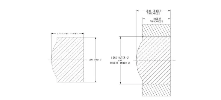

Figure 10-Mechanical drawing of LightPathPGM355110 (left) and IPGM355110 (right)
optical properties of molded glass lens
The mass inspection data for the 355110 lens contains typical ranges for five different interferometric measurements of wavefront error: RMS, P-V, astigmatism, coma and spherical aberration. Below is each distribution in the qualification lot of the current non-IPGM design for comparison with the IPGM lens values.
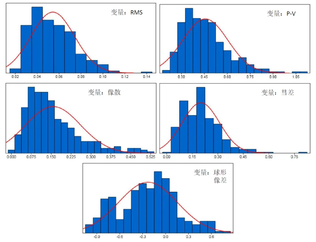
Figure 11 Optical performance data for non-IPGM lenses
The optical performance data for the lenses comes from the production lot after process engineering is completed, not from the process development stage. During the development process, process engineers are able to optimize process-related factors that may affect optical performance. Although hundreds of lenses are usually involved in this optimization process, the number of lenses used in this case is small because the process has proven to be feasible. All selected designs did not change the glass material, but only the insert material of the sample used for the interferometer measurement.
When molding CDGMD-ZLaF52LA glass, five different insert materials were selected, including stainless steel 410(SS410), brass, 6061T6 aluminum, Kovar alloy and stainless steel 304L(SS304L). Among these, the attempt to use 6061T6 aluminum as the insert material is particularly noteworthy. Since the forming temperature of the D-ZLaF52LA exceeds the melting point of aluminum, the aluminum insert partially melts during the forming process, causing it to adhere to the mold and glass. Obviously, aluminum is not suitable for the IPGM process of this glass material.
The other two designs used SS304L inserts and Kovar alloys with interface pressure values close to the edge of the acceptable range. SS304L inserts exert high pressure and induced stress on the glass due to their thermal expansion characteristics, while Kovar alloy inserts fail to hold the optics under very small forces. The data measured on the interferometer for a sample of the lens remaining in the Kovar alloy insert is as follows. It should be pointed out that because the process has not been fully optimized, this is one of the first lenses to be molded, and its optical performance has been affected.
In contrast, the case of SS304L showed no evidence of lens cracking or detrimental stress. The interface pressure values for the brass and SS410 inserts are within acceptable ranges and are expected to be successful. The interferometer used to record these measurements was FisbaOptikuPhase20T. Once the process stabilizes, it can be observed that the lens in each case is optically as viable as its non-IPGM version of its predecessor, a result shown in Figure 11.
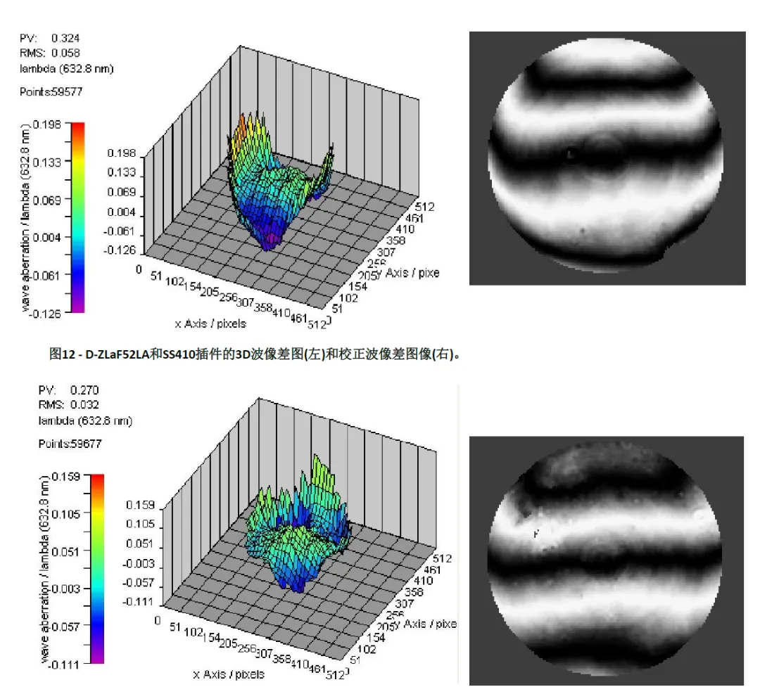
Figure 13-3D wave aberration image of D-ZLaF52LA and brass insert (left) and corrected wave aberration image (right)
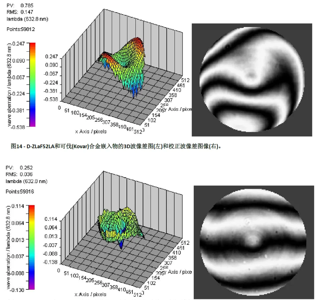
Figure 14-3D wave aberration diagram of D-ZLaF52LA and Kovar alloy inserts (left) and corrected wave aberration image (right)
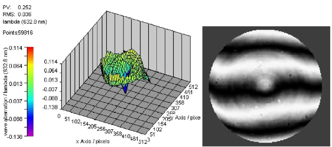
Figure 15-3D wave aberration image (left) and corrected wave aberration image (right) of D-ZLaF52LA and SS304L stainless steel inserts
bonding strength
The stability of the IPGM lens relies on a strong bond between the glass material and the metal insert, which may be chemical or mechanical. As previously discussed, the IPGM manufacturing process is feasible in some cases even if the interface pressure calculations show that the lens is in tension rather than compression. This type of bonding is thought to be due to a chemical interaction between the glass and the metal, but this paper does not explore this phenomenon in depth.
In the strength tests carried out, all the bonds tested showed the characteristics of mechanical adhesion, I .e. the metal insert applied a certain compressive force to the glass to maintain the bonding state of the two materials. The strength of the IPGM lens assembly is evaluated by using a vertical force test instrument, such as a ChatillonDFGS50 dynamometer. During the test, the vertical table descends at a rate of 12.7mm per minute until one of the following three conditions occurs: if the dynamometer reading reaches its maximum of 50 pounds, the test is terminated and the lens bond strength is determined to exceed 50 pounds; if the lens breaks without completely separating from the insert, it indicates that some part of the glass has weakened, and the maximum force value displayed on the dynamometer is recorded; if the lens can be pushed out of the insert intact and undamaged, the maximum force recorded is the push-out resistance of the lens and insert material combination.
The following is a summary table of the results of the different combinations tested to show the performance data of the various combinations tested in this article.
Table 4-Results of the push-out test, average force required to push out the optical lens.
The data in the table above reveals that different material combinations have different effects on the bond strength between the IPGM lens and the insert. In general, the higher the interfacial pressure, the stronger the bond between the two. With the exception of the combination using Kovar alloy, all other combinations using oxide glass D-ZLaF52LA, D-ZK3 and H-QK3L achieved a maximum reading of 50 lbs on the dynamometer with the lens still firmly held on the holder and the glass did not suffer any damage during the test.
However, in the case of using Kovar alloy as an insert, the bonding force generated by the interface pressure is extremely weak, many lenses fall off on their own without any applied force, and the force required to remove the remaining lenses from the insert is very small. This suggests that the design of Kovar alloys may be near the critical point where net zero force is generated, and the actual interface pressure may fluctuate between small tensile and compressive forces due to the existence of machining tolerances.
The IPGM lens design of chalcogenide glass is different from other types of glass design, and its test results should not be directly compared with other types of glass. Instead, the results of chalcogenide glasses should be compared with their own historical data and the performance when using different insert materials. For more detailed information on the design of chalcogenide glass IPGM lenses, reference can be made to document 21. Similar to the other designs discussed earlier, the Kovar alloy here also exhibits the weakest bond, with an average of just 18.7 pounds of force separating the components without destroying the optical properties of the glass. The stronger bonding between chalcogenide glasses and Kovar alloys seems to indicate that there are different interactions between the glass and the metal. In addition to the basic compressive force, there may be other types of bonding forces that play a role in the IPGM process. Chalcogenide glasses, which typically have lower interfacial pressures, are designed to better withstand the force of the push-out test, indicating that chalcogenide glasses can still form a strong bond with the insert even at lower interfacial pressures. For the non-chalcogenide glass equivalent design, all remaining designs required at least 42.99 pounds of force to successfully remove the optical lens from the insert.
hermetic seal
In certain applications, it may be critical to ensure the hermeticity between the optical lens and the mechanical insert. Similar to the embedding strength test discussed earlier, achieving a hermetic seal also requires that there be a certain bond between the glass and the insert material to prevent gas from penetrating through the interface between the two. The proper operation of many devices depends on this sealing performance, and laser systems are one of them. They often need to rely on sealing performance in infrared applications.
With the increasing use of shaped chalcogenide glasses in advanced manufacturing technologies such as IPGM, it is particularly important to evaluate the hermeticity of these glass types.
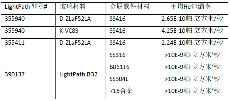
In order to test the air tightness, LightPath brands of lenses were selected, and the helium leakage rate was measured using SFJ261 helium mass spectrometer. Experiments involving various combinations of glass with different embedding materials have shown that these combinations exhibit sealing performance comparable to epoxy bonded components. The following table summarizes the results of the tightness tests. It is recommended that all IPGM designs requiring hermetic sealing be specifically tested to ensure that they meet the specific needs of the end application.
Table 5-He Leakage Rate Test Results of LightPath IPGM Lens

polarization destruction
In addition to the use of randomly polarized light sources in optical performance testing, such as used to generate the interferometers of FIGS. 12-15 previously described, polarized light sources are also commonly used in optical systems that may include IPGM lenses. Considering the possibility of introducing stress in the lens by the molding process, previous studies have explored the effect of such stress on polarization. It has been demonstrated in conventional PGM processes that stress conditions can be created in the lens. During the IPGM process, as the metal insert cools and shrinks, stress may be introduced into the glass, which in turn leads to birefringence, which may further destroy polarized light.
The refractive index of a transparent material changes with stress, so when stress is introduced into the material, stress birefringence occurs. This birefringence is due to refractive index changes in the plane of polarized light, resulting in a phase delay of the polarized light. Although the relationship between the principal stress and the amount of phase retardation can be established, the purpose of this article is to show that the IPGM process may cause the destruction of the polarization state, and discuss its potential impact.
In order to evaluate whether the IPGM lens has an effect on the polarization state of the passing light, a polarized light source with a wavelength λ = 488nm was used in the experiment. The beam of the light source passes through a linear polarizer aligned with the rotating stage, and a detector is placed at the end of the system. When the linear polarizer is adjusted to be parallel to the polarization direction of the light source, the transmitted light reaches a maximum, at which time the detector is set to 0dB attenuation with this transmission as a reference. The linear polarizer is then rotated to a position orthogonal to the polarization direction of the light source until the beam is attenuated to a minimum.
For non-IPGM lenses, the maximum value of attenuation is typically around 31dB, and the transmission is relatively stable in the range of 31dB to 29dB as the lens rotates. These measurements show that the PGM lens of this design does not introduce significant stress modes in the lens. To further investigate this phenomenon, a simple polarizer was used to capture images in order to visually observe the stress birefringence pattern.
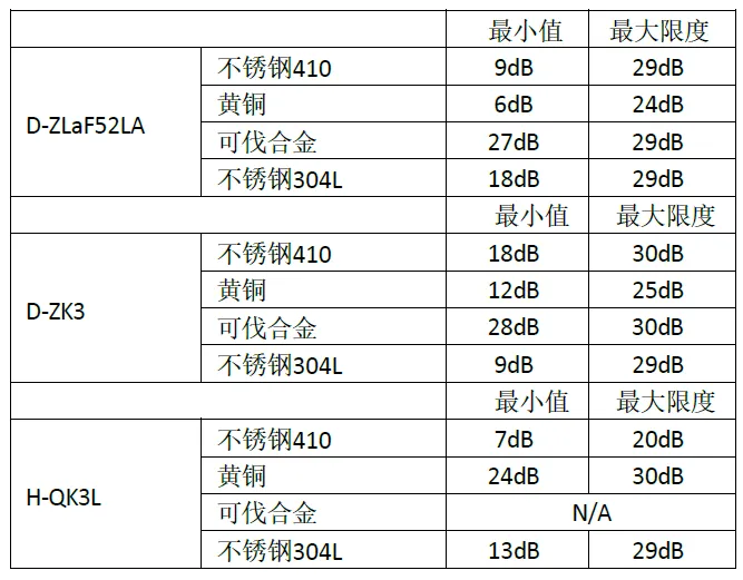
Figure 16-PGM Lens Polarometer Image
Figure 16 demonstrates the small degree of polarization perturbation of the lens over the physical aperture, which can be observed from the absence of the light-dark transition region. Although the non-IPGM lens presents a slight cross pattern to the naked eye, this subtle contrast change is difficult for the camera to capture. This pattern reflects the change in attenuation when the lens is rotated in the polarization test setup.
In the study, the polarization effects were analyzed for IPGM designs including four different embedding materials and three different glass materials. The embedding materials chosen were the same as those used in the previous interferometer measurements, including SS410, brass, Kovar alloy and SS304L stainless steel. Each insert material is used to mold three different types of glass: CDGMD-ZLaF52LA, CDGMD-ZK3, and CDGMH-QK3L.
After several rounds of testing on the IPGM lens, it is found that some embedding materials have some influence on the polarization state. As expected, the Kovar alloy insert had little effect on polarization due to the low interface pressure. Both stainless steels showed similar effects on all glasses tested. The brass molded lens, while also showing some effect, has a slightly different pattern as the lens is rotated compared to the stainless steel molded lens. The following table summarizes the measurement range for each configuration during lens rotation.
Table 6-Polarization Drift Test Results-Maximum and Minimum Attenuation Between Two Polarizers
To further confirm the phenomenon observed with the polarization test apparatus, the IPGM lens was imaged by using a simple polarizer to observe its stress pattern. As expected by the test, the two stainless steel insert molded lenses showed similar stress patterns, while the brass insert produced a different pattern. Specifically, the steel insert introduces a cruciform stress pattern in the lens as a result of typical uniform radial stresses. In contrast, the pattern formed by the brass insert is slightly different, as the two semi-arcs extend from the ends of the lens and are not connected at the center. This difference may explain why the brass inserts showed improved performance compared to the stainless steel inserts in the tests.
Kovar alloy inserts induce almost no stress in the lens and produce patterns very similar to non-IPGM lenses, showing very low stress effects. Below are photographs of different materials and their corresponding stress patterns. Since no photograph of the Kovar alloy lens remains in the glass-H-QK3L insert, it is omitted here.

Figure 17-D-ZLaF52LA Polarometer image. From upper left corner SS410, brass, Kovar, SS304L
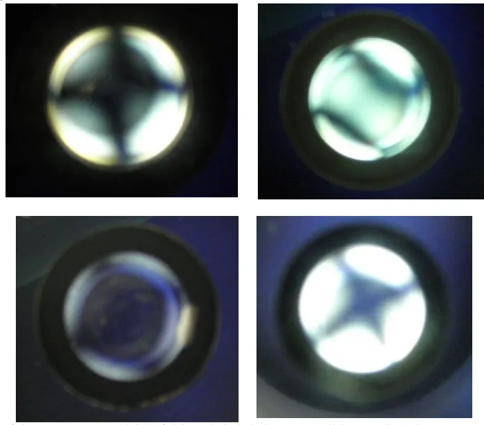
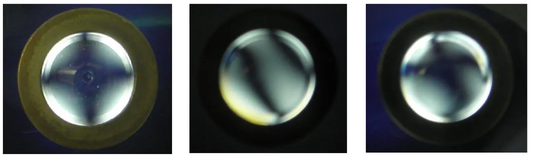
Figure 18-D-ZK3 Polarization Instrument Image. From upper left corner SS410, brass, Kovar, SS304L
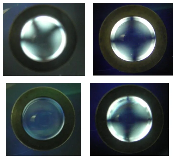
Figure 19-H-QK3L Polarimeter image. Left to right SS410, Brass, SS304L
aspheric profile
The aspheric surface of the optical lens is formed by precision machining a special mold. This basic manufacturing method from PGM (glass precision molding) to IPGM (embedded glass precision molding) remains unchanged. The entire production process relies on a mold whose surface can be reused in multiple molding processes until its surface quality degrades to the point where a new mold needs to be made. Therefore, verifying that the mold surface can accurately replicate its design on the lens surface is a critical step. While an interferometer test similar to the one mentioned earlier can confirm that a lens is working as designed, such a test is not always applicable to all types of lenses. In general, understanding how the shape is transferred from the mold to the glass lens is beneficial for improving the mold manufacturing process. Ideally, a combination of interferometer testing and profilometry measurements can provide more reliable results for evaluating the success of a design.
When molding a lens, problems may be encountered with increased stress on the lens, which may result in distortion of the designed surface profile of the lens. In order to determine the profile of the mold used in the IPGM process and compare it with the lens surface, a TaylorHobson Talysurf profilometer was used. Below is the surface profile data for the two aspheric molds used to fabricate the lenses in this experiment.
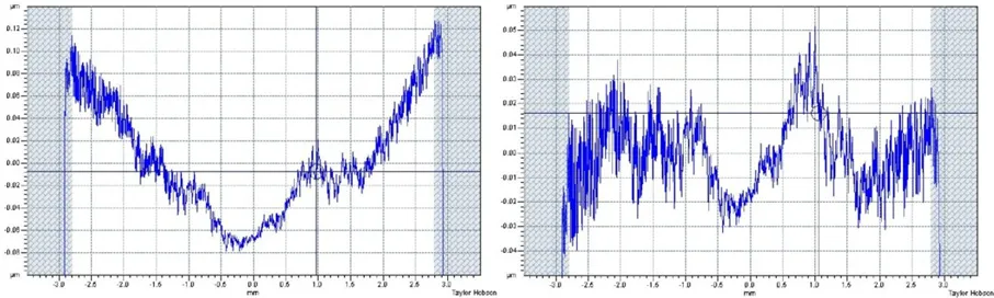
Figure 20-Mold #1 surface shape diagram (left) and optimized radius shape diagram (right)
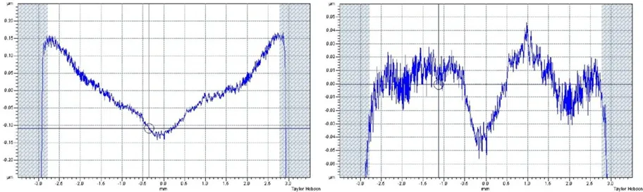
Figure 21-Mold #2 surface shape diagram (left) and optimized radius shape diagram (right)
These values intuitively reflect the accuracy of the mold surface profile. For the first mold, as shown in Figure 20, the root mean square (RMS) error of the surface shape map is 47nm, and after radius optimization, the deviation between the design radius and the best fit radius is 0.959um. The RMS error of the optimized radius map is reduced to 14.6nm. For the second mold, as shown in FIG. 21, the measured RMS error is 80nm and the radius-optimized deviation value is 1.680um. After radius optimization, the RMS error of the second mold is reduced to 17.7nm. These measurements are within the standard tolerances of mold manufacturing.
The profile of the mold is slightly adjusted to compensate for expected changes in shape due to differences in material shrinkage and thermal expansion. After verifying through measurement that the mold meets the tolerance requirements for manufacturing high-quality lenses, the mold is used in a molding machine. According to the procedure described in FIG. 1, the lens was manufactured and measured in the same way as the mold. These measurements are then compared with the optical performance data from the interferometer to ensure that the final product meets the desired design criteria. Following the principle of "function over form", optical performance is usually regarded as a more critical indicator than surface form. However, the combination of these two measurements provides comprehensive verification of the success of the design. The following are the results of surface shape maps and optimized radius maps for different glass material and insert material combinations.
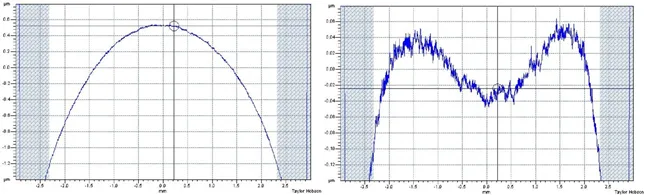
Figure 22-Surface profile of stainless steel 410 insert D-ZLaF52LA lens (left) and profile after radius optimization (right)
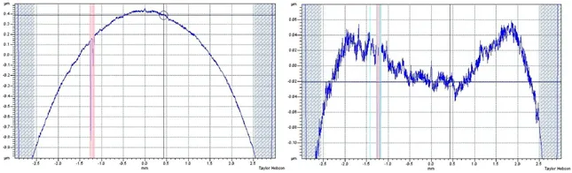
Figure 23-Brass insert D-ZLaF52LA lens surface shape diagram (left) and optimized radius shape diagram (right)
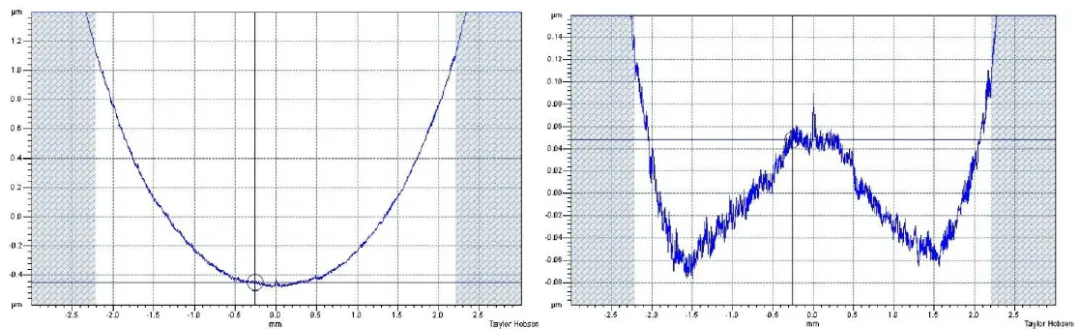
Figure 24-Surface shape of Kovar alloy insert D-ZLaF52LA lens (left) and shape after radius optimization (right)

Figure 25-Surface profile of stainless steel 304L insert D-ZLaF52LA lens (left) and profile after radius optimization (right)
These measurement data reveal a slight deviation in the target design radius for all combinations using D-ZLaF52LA glass. Specifically, the difference between the optimized radius of the SS410 insert and the design radius is -15.5um; the difference between the brass insert and the design radius is -9.9um; and the difference between the SS304L insert is -8.8um. The shorter radius in these three cases indicates that the shrinkage of the insert during the cooling process has a certain compressive effect on the lens shape.
In contrast, the situation is different for Kovar alloy inserts, whose optimized radius is plus 16.6um more than the design radius. This indicates that the Kovar alloy insert may not exert a compressive force on the glass, but may instead exert a tensile force, which causes the glass to expand beyond the design radius, or through chemical bonding or other types of bonding between the insert and the glass, such that the radius becomes longer.
Although none of these lenses fully achieved the design radius, and thus slightly deviated from the design shape, their RMS error and best-fit RMS error values were still within or very close to typical manufacturing tolerances. In terms of specific values, the RMS error of the SS410 insert assembly is 50.6nm, which is reduced to 34.5nm after optimization. The RMS error of the brass insert is 33.4nm, which is reduced to 20.1nm after optimization. The RMS error of the Kovar alloy insert is 59.3nm, which increases slightly to 64.9nm after optimization. The RMS error of the SS304L insert assembly is 35.8nm, which is reduced to 24.8nm after optimization.
It is important to note that all of these lenses passed the test of optical performance, although the shape parameters of some lenses may approach or slightly exceed the limits of PGM fabrication. The surface shape data provides more comprehensive information about the lens performance, which can help to understand the actual performance of the lens.
Advantages and design considerations of the molded glass process
Embedded glass precision press molding (IPGM) technology has proven to be a suitable manufacturing technology for a variety of optical systems and applications. It facilitates the assembly of large IPGM arrays, from precision molding of high-index glass with metal inserts to the combination of chalcogenide glass and metal inserts for quantum cascade lasers. IPGM technology simplifies the control of the center of the optical element, and its accuracy is mainly limited by the capabilities of the processing technology. Similar to plastic injection molded optical components, IPGM allows for the incorporation of mechanical features into the insert design that can be used for alignment or mounting of the components. In addition, the metal surface of the insert can also be directly welded to the final component without the use of epoxy resin or other additional materials, which greatly expands its application range.
In order to ensure the effectiveness of IPGM component design, the following key factors must be carefully considered. Material selection is critical to the success of the IPGM design, because the difference between the coefficient of thermal expansion (CTE) of the glass and the insert will determine whether compression or tension is generated at the interface. If the interface pressure is too low, the fit between the components may not be tight, which may cause the optical lens to fall off; and if the interface pressure is too high, the glass may be subjected to excessive pressure, causing cracking or serious degradation of optical performance. After the material selection is completed, it must be ensured that the volume of the glass preform and the insert match. By adopting good design practices, such as reducing the acute angle on the mold by increasing the counterbore diameter, the service life of the mold can be extended and the manufacturability of the product can be improved. Following appropriate design criteria, IPGM is a viable method of manufacturing precision optics, with advantages such as simplified installation, direct soldering to the final assembly, improved centering accuracy, and the avoidance of foreign materials such as epoxy.
IPGM Manufacturing Limits
IPGM lenses and PGM lenses are basically similar in optical characteristics, but there are some differences in their design and manufacturing processes. One major challenge facing IPGM lens design is bond strength. Unlike PGM lenses, IPGM lenses typically require the use of a separate holder or other component. This bonding may result in increased interface pressure due to thermal expansion mismatch and other factors. Experimental results show that IPGM lens designs with higher interface pressures require more force to be removed from the insert.
In terms of material selection, Kovar alloy proved to be the least efficient material for making monolithic IPGM components. This may be due to a chemical reaction between the alloy and the glass or other factors resulting in insufficient bonding strength. On the contrary, other bonding methods between glass and metal may be the key factor to improve the bonding strength of IPGM components, but further research is needed to understand this phenomenon in depth.
Related to the joint strength is the sealability of the IPGM assembly. He leak tests designed for IPGM components have shown that these components can form a nearly hermetic seal. This sealing is essential to maintain the optical performance of the lens, because it prevents contaminants and moisture from entering the inside of the lens, thereby affecting its performance.
In addition, the stresses and strains present in IPGM lens designs have a significant effect on the profile of the lens optical surfaces. The compressive force will cause the radius of the convex lens to become smaller, while the net zero or partial tension will cause the radius of the convex lens to become larger. This surface change may affect the focusing power and imaging quality of the lens.
When the lens is rotated in the polarized beam, the stress in the glass can cause birefringence and produce a polarization shift. The polarimeter can show the stress pattern in the lens, and the lower interface pressure design has less influence on the polarization of the beam passing through the optics. This means that in order to maintain the optical performance of the lens, the interface pressure and tension needs to be carefully controlled during the design and manufacturing process.
In summary, IPGM lenses are designed and manufactured to take into account a number of factors, including bond strength, sealability, and surface variations.
Advantages of molded glass products
① Do not need the traditional rough grinding, fine grinding, polishing, grinding edge centering and other processes, can make the optical components to achieve high dimensional accuracy, surface accuracy and surface finish;
② can save a lot of tooling accessories, production equipment, plant area and skilled workers, and has a high manufacturing capacity, to achieve the mass production of precision aspheric optical components;
③The production process is simplified, as long as the temperature and pressure in the molding process are accurately controlled, the consistency of the quality and performance of optical components can be guaranteed;
④ Very suitable for molding small aspheric lenses, optical components and assembly reference parts can be made as a whole.
Chalcogenide glass molding process is a comprehensive technology, which requires the use of high-quality molds and the selection of reasonable process parameters, the design of special molding machine tools. At present, the diameter of the molded aspheric optical elements that can be mass produced by wavelength optoelectronics is 1~25mm, and the diameter tolerance is ± 0.01mm; the thickness is 0.4~10mm, and the thickness tolerance is ± 0.01mm; the radius of curvature can reach 5mm; the surface shape accuracy is 1.5 λ, and the surface finish conforms to the US military standard of 40-20.
Process tuning for mass production of molded glass
(1) Molding equipment. The test adopts the DTK-LMR-3300A8 molding equipment of South Korea DTK Company, which is an 8-station molding machine. The molding chamber of the equipment is composed of pressure control system, heating system, cooling system and conveying system. The highest molding temperature is 700 ℃, the maximum pressure is 1MPa, and the maximum mold diameter is 60mm, which can realize continuous production of multiple molds.
Molding process:
Molding process flow
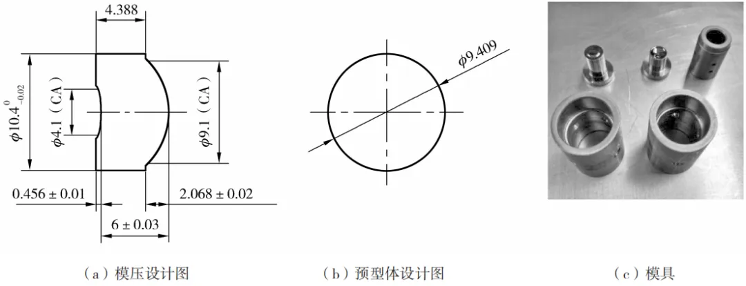
(2) Molding design. The design of the product is double-sided aspheric ASP1 is concave and ASP2 is convex. The lens is convex and concave with a diameter of 10.4mm. The effective diameters of ASP1 and ASP2 are 4.1mm and 9.1mm respectively, and the center thickness of the lens is 6mm. Lens design requirements: molded lens PV≤ 0.5mm.
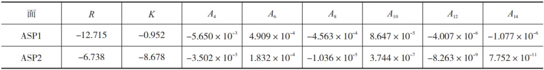
aspheric curve parameters

According to the lens shape, a mold design (a), a preform design (B) and a mold design were carried out. IRG209 chalcogenide glass produced by Hubei Xinhuaguang Information Materials Co., Ltd. was used in the test. The test preform is designed as a spherical preform with a diameter of 9.04mm, and the surface polishing treatment meets the requirements of optical mirror surface, and the appearance grade is 60/40. The mold for press molding is South Korea N18 hard material (c), and the surface of the mold is plated with a Ta-C release film.
Molding Design and Analysis of Mold Physical Figure Results
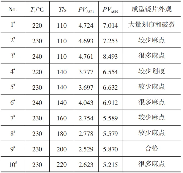
(1) The relationship between molding process and lens surface defects. DTK molding machine is a continuous production mode, all stations (t1-t8) time is equal, that is, molding cycle t. According to the transition temperature (Tg = 190 ℃) and sag temperature (Ts = 210 ℃) of IRG209 chalcogenide glass, 10 molding processes in Table 2 are formulated. The difference of the processes is that the molding temperature T4 is different from the molding cycle t. In order to simulate the mass production conditions, 10 sets of the same mold were put into the molding equipment to test the average PV of the lens after molding and the defect of the lens surface.
Molding process and molded lens test results
Picture
When the T4 temperature is high, the defective surface of the molded lens is serious. Under the 11W fluorescent lamp, the surface of the molded lens is densely pitted, and some Products parts have ring-shaped pits. Reasons for the defects: under the condition of high temperature molding, chemical reaction occurs on the glass surface to form volatile gas. The central part of the glass always contacts the center of the mold. During molding, volatiles gather in the closed space to form ring-shaped pits on the extruded glass surface, while other areas gradually contact the molding surface of the mold from the inside to the outside, without forming a closed space. Volatile gas directly escapes from the mold cavity.
When the T4 temperature is low, the surface of the molded lens has a large proportion of scratches and cracks. The reason for this kind of bad: under the condition of low temperature molding, the glass viscosity is large and the ductility is poor, and the friction with the mold surface during molding and extrusion will produce scratches, and even rupture. Prolonged molding cycle t, poor rupture improved.
The 9# process molded lens has the best appearance and is the best molding process, but under this process, the lens surface accuracy PVASP1 = 2.529mm(a)) and PVASP2 = 5.870mm (B) do not meet the optical design requirements. In the study, a mold correction was carried out to compensate the offset of the lens surface on the mold. After the mold is corrected, the 9# process is used again for molding. The surface accuracy of the molded lens is PVASP1 = 0.259mm(c) and PVASP2 = 0.206mm(d), which meets the design requirements.
Molded lens PV value
(2) the change of specific gravity before and after molding. The specific gravity change of chalcogenide glass before and after molding was tested by "drainage weight loss method. See the following table for specific gravity of glass before and after molding. After molding, the specific gravity of the glass decreases, and the faster the cooling rate, the greater the degree of reduction in specific gravity.
Specific Gravity of Chalcogenide Glass Before and After Molding
The reason for this phenomenon: According to the theory of stress relaxation, the glass is gradually transformed from viscoplastic elastomer to elastomer in the process of precision molding annealing, and the effect of stress relaxation can only eliminate the stress part in the temperature difference. When the glass is cooled below the strain temperature, the internal stress generated in the glass, the internal stress remaining in the glass is just the part where the stress relaxes, forming a permanent stress. In this process, the thermal motion energy of the internal molecules of the glass is small, the internal structural group cannot shift to offset the internal stress generated by the temperature difference, the glass structure is in a fluffy state, the glass volume expands, and the specific gravity decreases. The faster the cooling rate of the glass, the greater the permanent stress inside the glass and the smaller the specific gravity of the glass.
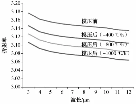
(3) Refractive index change before and after molding. All-European goniometer (SpectroMaster®) The refractive index of chalcogenide glass before and after molding was tested, and the refractive index data of the glass before and after molding were compared. The curve of the refractive index of the glass before and after molding shows that the refractive index of the glass decreases after molding, and the faster the cooling speed, the greater the degree of refractive index reduction.

Refractive index of chalcogenide glass before and after molding
In the molding test of Ge-Se-Te sulfur-based glass aspheric lens, the best molding process of the product was obtained through 10 groups of process tests, and the reasons for the surface defects of the molding process were analyzed. Through a mold correction, a molded lens with a lens surface accuracy of PVASP1 = 0.259mm and PVASP2 = 0.206mm was prepared to meet the design requirements. In the study, it is found that the refractive index and specific gravity of Ge-Se-Te glass after molding are lower than those before molding, and the faster the cooling rate of molding, the greater the decline in refractive index and specific gravity of molded lenses. Through the relaxation theory, it is known that the permanent stress inside the glass in the molding process changes the glass structure, the glass volume expands, and the specific gravity decreases. At the same time, due to the change of the external field, the specific gravity is reduced, and the refractive index is also reduced.
Application of Molding Technology of Chalcogenide Glass
Wavelength Optoelectronics has professional molding and detection equipment, which can be used to mass produce aspheric molded glass lenses molded by ultra-precision aspheric molds at high temperature, and to manufacture aspheric lenses for optical fiber couplers for optical communication. Molded glass lenses have the characteristics of stable quality, good consistency and suitable for continuous mass production, and can be widely used in mobile phones, vehicle/unmanned aerial vehicles, medical treatment, projection, monitoring, smart furniture, AR/VR and other application fields.
Grade and Characteristics of Chalcogenide Glass
At present, foreign chalcogenide glass is mainly AMTIR-1, 2, 3, 4, 5, 6 series produced by Amor-phous companies in the United States, IG2, 3, 4, 5, 6 series produced by Vitron companies in Germany, and GASIR1, 2, 3 series produced by Umicore companies in France.
Domestic chalcogenide glass is mainly HWS1, 2, 3, 4, 5 and 6 series produced by Chengdu Guangming Opto-electronic Co., Ltd., IRG201, 202, 203, 204, 205 and 206 series produced by Hubei Xinhuaguang Information Materials Co., Ltd., and NBU-IR1, 2, 3, 4, 5, 6, 7 and 8 series developed by Ningbo University.
Among them, 1G6 products are currently used more in the long-wave infrared band, and the domestic glass grades with the same optical parameters are HWS6, IRG206 and NBU-IR5.
Status Quo of Chalcogenide Glass Abroad
Infrared chalcogenide glass materials have been applied for more than 60 years, but at present, there are mainly 3 enterprises that have achieved industrial production and commercial application of infrared chalcogenide glass materials in the world, and they are AmorphousMaterialsInc in the United States, VitronGmbH in Germany and UmicoreElectro-OpticMaterials(EOM) in France. Among them, AMI in the United States provides about 1 ton of chalcogenide glass products to the military or civilian market every year. Due to the sensitivity to the application of infrared materials in the military field and the monopoly of the product market, these foreign companies strictly block the preparation technology of chalcogenide glass materials, and do not open branch production in China.
(1)UmicoreElectro-OpticMaterials(EOM)
EOM's main business in infrared materials is Ge and GASIR.®, where GASIR®For chalcogenide glass materials, we can provide raw materials, blanks, spherical lenses, aspheric and aspheric diffractive lenses and other optical components and components. GASIR®5 Equivalent to grades IG6 and IRG26 chalcogenide glass, with a maximum diameter of 200mm. It has a high refractive index and a thermal expansion coefficient close to that of aluminum, which can reduce the structure and cost of the optical system while maintaining the best non-thermal performance. GASIR®1 has good mechanical properties, excellent optical properties and moldability.
(2)德国VitronGmbH
VitronGmbH, Germany, is mainly engaged in the production and sales of ZnS, chalcogenide glass infrared optical materials and infrared optical components. Vitron has five different brands of chalcogenide glass materials of IG-2, IG-3, IG-4, IG-5 and IG-6, which can provide f5 ~ 150mm materials, blanks and optical devices. Vitron has a certain popularity in the world and has a considerable market share and competitiveness.
(3) German SCHOTTAG
German SCHOTTAG is a multinational high-tech group company founded in 1884. He has 130 years of industry experience in optics, glass manufacturing and advanced technology. Its main businesses include household appliances, medicine, electronics, optics and transportation. Global sales amounted to € 2.05 billion billion in 2016/2017, with production sites and sales offices in 34 countries. Relying on its strong technical strength, SCHOTTAG advanced optics division is committed to product development and customization in the fields of optics, lithography technology, astronomy, optoelectronics, architecture, life science and research. It has a product portfolio of more than 120 kinds of optical glass, special materials and components, and has an overall value chain from personalized customization of glass products to high-precision optical product processing and measurement. Its infrared optical materials are mainly chalcogenide glass, sapphire and ZnS, of which chalcogenide glass has five models of IRG22, IRG23, IRG24, IRG25 and IRG26, with a maximum size of 100mm in diameter and 150mm in length.
(4)美国AmorphousMaterialsInc.(AMI)
AMI was founded in 1977 primarily to produce infrared transmitting glass or infrared glass optical materials for use as night vision (FLIR) systems. The term "Amorphous" is used to indicate the non-crystalline nature of infrared glasses. AMI supplies chalcogenide glass materials with grades of AMTIR-1, AMTIR-2, AMTIR-4, AMTIR-5, AMTIR-6 and AMTIR-7. AMTIR is the abbreviation of "amorphousmaterialtransmittingIRradiation". AMI also provides optical grade GaAs.
With the help and support of the US Army Night Vision Laboratory, AMI has developed infrared chalcogenide glass material preparation technology and established equipment and production lines with a production capacity of 10000 pounds per year. AMI is purified by distillation in a high-purity quartz container under computer control to produce flat chalcogenide glass sheets with a diameter of 200mm and a weight of 20 pounds, which are used to make the required lens blanks or optical elements. AMI does not manufacture finished optical devices, but only small diameter, short focal length AMTIR lenses for commercial passive infrared devices for remote temperature detection.
The chalcogenide glass produced by the above-mentioned companies is mainly As, Se-based glass system, the application is mainly concentrated in the near-infrared-mid-infrared-far-infrared band range, its products and technology has been quite mature, almost monopolizing the global infrared chalcogenide glass material market. Infrared chalcogenide glass has moldability, and can be processed in batches by precision molding process, thereby reducing the production and processing costs of optical components. At present, the United States LightPathTechnologiesInc is well-known for the production of precision molding of chalcogenide glass abroad. and two UmicoreEOM companies in France. Among them, LightPath company in the United States is an enterprise specializing in the production and manufacture of sulfur-based glass precision molded lenses. Its largest market is in China. It has opened branches in Shanghai and Zhenjiang in my country to specialize in the sales of its precision molded products, occupying the Chinese market. Most of the market share. The French Umicore company is the only one in the world at the same time master chalcogenide glass preparation technology and precision molding technology manufacturers. In recent years, Ningbo Shunyu Infrared Technology Co., Ltd. has also built a precision molding production line for chalcogenide glass. Yunnan North Chihong Optoelectronics Co., Ltd. uses traditional optical element processing technology and single-point diamond turning technology to process chalcogenide glass optical elements, and has developed a series of infrared optical lenses. It has long enjoyed a high reputation in infrared related fields at home and abroad.
Current Situation of Domestic Chalcogenide Glass
In China, East China University of Science and Technology, Wuhan University of Technology, Ningbo University, Xi'an University of Technology, Beijing Glass Research Institute, Shanghai Institute of Optics and Machinery, Beijing Nonferrous Metals Research Institute and other universities and scientific research institutions have carried out a lot of basic research work on infrared chalcogenide glass, Ningbo University has made a series of research results in the basic research field of chalcogenide glass. With the support of the preliminary research of the National 973 and the Zhejiang Provincial Science and Technology Department of Science and Technology and Technology and, after years of research, it has broken through the key technologies for the preparation of chalcogenide glass materials, independently developed a chalcogenide glass optical characteristics detection device, and has a number of patented technologies in the development of chalcogenide glass. At present, it has a relatively complete pilot production line, which has a high level in the research and development of chalcogenide glass preparation technology. In terms of industrial development and large-scale production, due to the progress and breakthroughs in both equipment and technology, as well as the market traction of infrared thermal imaging, night vision devices and other infrared equipment products, in recent years, the domestic production of chalcogenide glass industry is in full swing.
Beijing, Hubei, Chengdu, Ningbo and other places have bred a number of enterprises that produce infrared chalcogenide glass materials. Representative enterprises or units include Hubei Xinhuaguang Information Materials Co., Ltd., Youyan Guojinghui New Materials Co., Ltd. and Ningbo University Infrared Materials and Devices Laboratory. Hubei Xinhua Optical Information Material Co., Ltd. is one of the large production bases of special optical materials in China, with an annual output of 6038 tons of optical glass, 0.5 billion primary and secondary optical parts, 10 tons of special optical materials such as chalcogenide glass. Its infrared optical glass materials are mainly two series of mid-infrared material IRG1XX and far-infrared material IRG2XX, of which IRG2XX is chalcogenide glass material, which is also divided into 6 types according to different in composition, its model, composition and other product parameters are shown in Table 5. In terms of industrialization scale, product quality inspection, market share, etc., Hubei Xinhuaguang has special advantages and capabilities in China, and has certain influence and competitiveness in the domestic market. It can provide various shapes of blank products with diameter f7mm ~ f200mm, as well as infrared lenses and infrared lens products. On a global scale, there has been no unified relevant standards for the technical specifications and parameters of infrared chalcogenide glass products. It was learned from the Hubei Daily report that the three international standards for infrared optical glass formulated by the domestic Hubei Xinhuaguang Information Materials Co., Ltd. It was officially approved by the ISO International Organization for Standardization.
Ningbo sunshine and spectrum photoelectric technology co., ltd. was established in 2017. it is mainly engaged in the research, development, production and sales of infrared chalcogenide glass materials, photoelectric functional crystals and devices. the annual production capacity of chalcogenide glass materials is 2~3 tons, with a diameter of 26~120mm. its performance parameters are shown in table 6, the company's main technology relies on the infrared materials and devices research team of the Institute of Advanced Technology of Ningbo University and the crystal research team of the School of Materials Science and Chemical Engineering.
Youyan Guojinghui Company is mainly engaged in the R & D and production of infrared optical materials and high-purity chemicals for optical fibers. It has three production lines, such as CVD deposition, chemical purification for optical fibers and manufacturing of optical components. The main products include CVDZnS, CVDZnSe, high-purity germanium tetrachloride and silicon tetrachloride, sulfur-based infrared glass, etc, among them, chalcogenide glass has three types of products: GG1(Ge28Sb12Se60), GG2(Ge33As12Se55), GG3(Ge30As10Se60) and GG6(As40Se60), with a maximum diameter of 150mm. The products provided are in the form of blanks, polished parts, coated parts, etc.
It is worth mentioning that in recent years, a new enterprise in Yantai, Shandong Province, the chalcogenide glass of Hengbang New Materials is a rookie with rapid development in recent years. Its company's HBL series has excellent raw materials and excellent workmanship. The quality of the products is also fast and stable within a few years, gradually reaching the first-class level in the market. The company can mass-produce HBL201 to HBL207 a total of 7 grades of sulfur-based glass. According to customer requirements to provide a variety of forms of supply: such as blank blocks, pieces, lenses and balls, etc., can provide a diameter of Φ100mm within the specifications of the product.
Transfer from AIOT Big Data Public Number will be deleted if infringement.
Related News

We sincerely look forward to working with you!
Address
Card A, Room 103, No.39, Science and Technology East Road, Torch Development Zone, Zhongshan City
Telephone